Replication topologies
Cloudant’s (and CouchDB’s) replication feature allows you to keep databases in sync across countries and continents. However, sometimes it’s not obvious how to use this basic pair-wise feature in order to create more complicated replication topologies, like three or more geographical replicas, and then how to do disaster recovery between them. Let’s discuss these in turn.
Throughout the following, it’s important to remember that replication is an asynchronous, best-effort process in which a change is propagated to peers sometime after the client receives the response to its write request. This means that longer replication chains don’t directly affect document write latency, but also that discrepancies between peers will exist for some small period of time (typically low single digit seconds maximum) after a write to one peer completes.
More complicated topologies🔗
Firstly it’s important to understand that Cloudant’s replication creates synchronised copies of databases between peers once a two-way replication is set up. Each replication flows changes only in one direction, which means that a two-way replication involves setting up two separate replications, one in each direction. Visualising this as a directed graph works well. Each node in the graph is a Cloudant database and the arrows are directed edges showing which way changes are flowing.
Using this style, a basic two-peer setup between databases A and B looks like this:
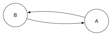
There are two arrows because to have synchronised peers a replication needs to be set up in each direction. After a very short time – milliseconds to seconds – peer A will know about any changes to B, and, similarly, B will know about any changes to A.
These peers can then further replicate with other peers to support more complicated scenarios than a single pair of peers. The key point is that, by setting up replications, one is setting up a graph that changes traverse to get from one peer to another. In order for a change to get from peer A to peer Z, at least one directed link must exist between A and Z. This is the foundation piece to creating more complicated topologies because either A or B can now replicate the changes elsewhere.
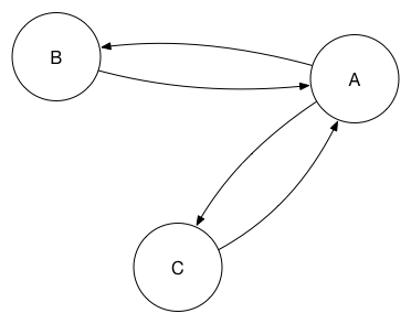
So A can propagate the changes from B to another database, C. In this scenario, A is the primary database and the others could be considered replicas.
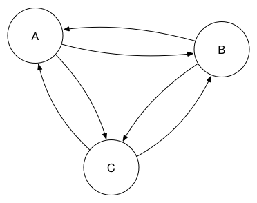
This obviously introduces a single point of failure. The replication process is smart enough that you can add a replication from B to C to this set, which means that A is no longer a single point of failure. In graph terms, it’s safe to set up a cyclic graph.
As more database replicas are added to the set, however, having a fully connected mesh starts to add undue load to each database, and it’s not necessary as each peer is able to act as a “stepping stone” to push changes through the network.
Here, a change at peer B is replicated to E via A then C:
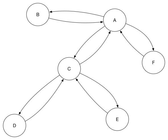
In the diagram I only have one stepping stone in each path for simplicity of diagramming, but one could add redundant steps to ensure at least two paths through the network for any given change.
Using One-Way Replications for Synchronisation between Peers🔗
Finally, it’s worth revisiting the point that all we require for synchronisation is that there is a directed path for a change to follow from one peer to another. This means that two-way replications between peers are not strictly required. Instead, one alternative is to set up a circle topology:
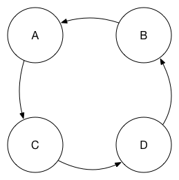
Here, there is still a path for changes to follow between any pair of nodes. Again, setting up redundant links to provide two paths may be useful. Using one-way replications in this way further allows you to decrease the load upon each peer database while still maintaining acceptable replication latency.
Failing over between databases🔗
After setting up the synchronised peers in whatever topology works for your needs, you’re ready to set up failover between the database replicas.
The important takeaway point in this section is that, while you might be tempted to manage failover elsewhere, the only way to reliably failover is from within the application itself. The reason for this is simple: the application is the only place you can be sure whether a given replica is contactable from the application.
An application may be unable to contact a database peer for several reasons, such as:
- The database servers are actually offline.
- The application cannot route to the preferred database servers because of network disruption.
- There is very high latency suddenly introduced on the network path between the application and database clusters.
- The application’s DNS cache is out of date so it’s resolving the database location to the wrong IP address.
- Key database requests made by the application have a latency above a given threshold.
The last condition is an example of how the application can use its own measurements to ensure failover happens before users become aware of the problem and how a failover strategy can benefit from being application performance-indicator aware.
The only thing you care about is whether the application can reach the database; not whether, for example, the third-party health-checking service you might use can contact it, or your DNS provider.
The basic steps are:
- Configure each application instance with a prioritised list of database peers.
- Use an approach like the circuit breaker pattern to guide failover.
- Progress down the prioritised list.
- Have a background task checking for recovery of higher priority peers, failing back when they are reliably available to the application again.
This approach is simple to understand, not too complicated to implement and gives your application the best chance of surviving the most number of possible failure modes.